
Got a hot‑tub plumbing diagram and feel lost? Here’s a clear, step‑by‑step walk‑through that turns that maze of pipes into a picture you can actually read.
Step 1: Identify Your Hot Tub’s Main Components
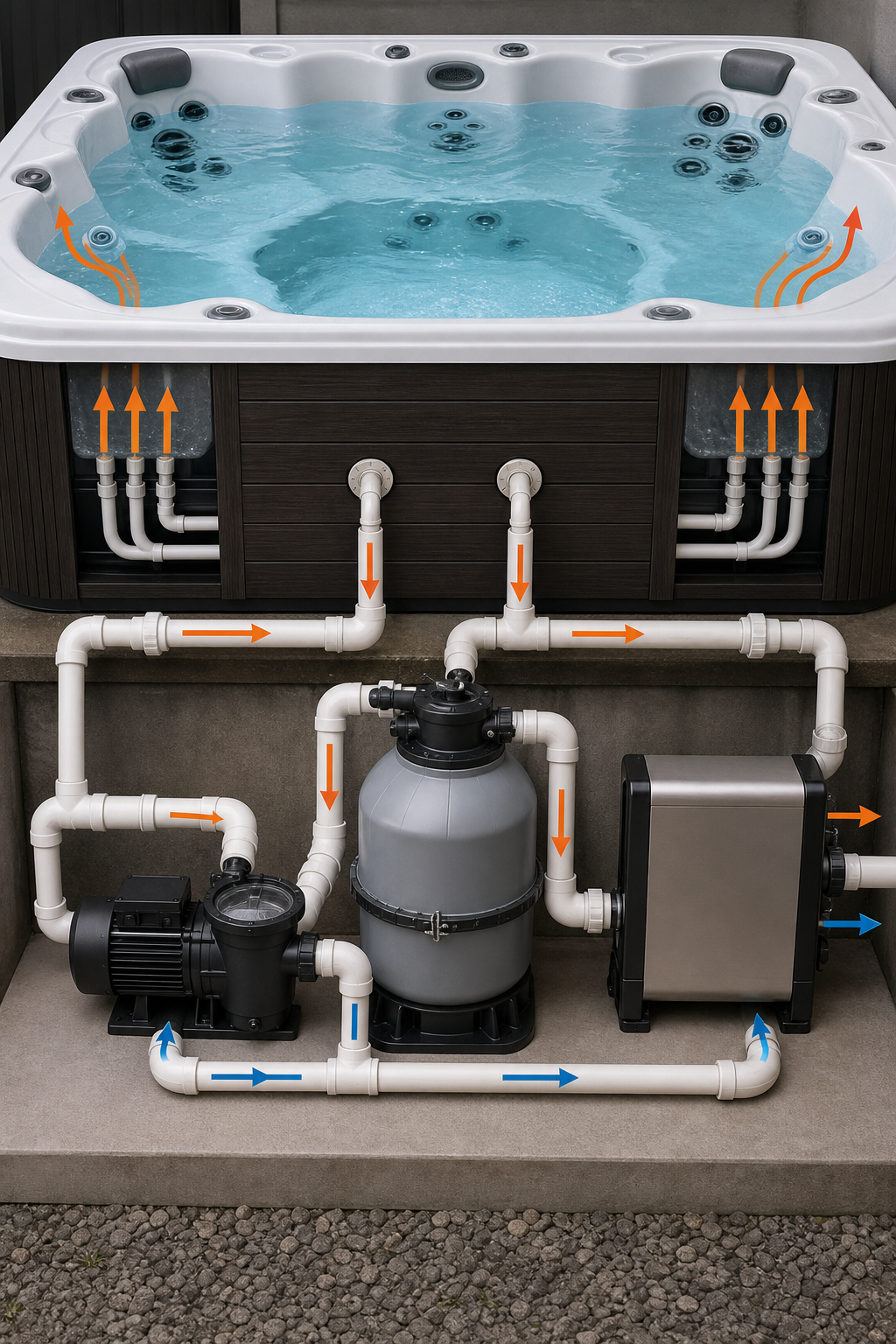
Every hot tub has a handful of core pieces that show up on any schematic. The shell houses the water. A circulation pump pulls water from the bottom, pushes it through a filter, then sends it to a heater. After heating, the water returns to the shell through jets, air injectors, or a waterfall. Control valves let you route flow to different jet groups. The diagram will label each part with a short tag , “P” for pump, “H” for heater, “F” for filter, etc.
Knowing what each symbol means stops you from guessing. Standard references break down the typical component list and explain why the pump sits near the bottom (it needs the deepest water for proper suction). A good diagram also marks the electrical disconnect, a safety requirement that keeps the water and power separate.
For owners in desert climates like the Coachella Valley, the pump and heater must handle extreme heat and mineral‑rich water. Luxury Hot Tubs works with Caldera® spas that place the pump in a sealed cabinet and use corrosion‑resistant PVC, which shows up on the plan as a thicker line. Spotting those extra‑wide pipes early tells you the system is built for hard water.
Bottom line: match each symbol on the drawing to the real part in your spa. When you can point to the pump, the filter, and the heater, the rest of the diagram becomes readable.
Step 2: Map the Water Inlet and Outlet Paths
The next thing to trace is how water moves from the tub back to the tub. Start at the suction fittings , usually two drains on the floor. From there the pipe leads to the pump inlet. After the pump, the flow may split: one branch heads to the filter, the other heads straight to the heater. Once the water passes the heating element, it flows out through return lines to the jets.
Technical bulletins describe two common flow configurations. A “parallel” layout runs separate inlet and outlet lines for each heater, while a “series” layout strings one heater’s outlet into the next heater’s inlet. Your diagram will label the configuration with a letter or a note. Knowing which style you have helps you predict pressure drops and filter placement.
Follow the arrows on the plan. If the arrow loops back to the same pipe, you’re looking at a series setup. If two arrows run side‑by‑side from the pump to two heaters, that’s a parallel layout. The path you draw on a sheet of paper should mirror these arrows exactly , that’s how you’ll spot errors later.
Pro Tip: use a different colored pen for the inlet line and the outlet line. It makes the loop instantly obvious.
Step 3: Understand Heater and Pump Flow Configurations
The heater and pump are the heart of the system. The pump creates the pressure that pushes water through the heater’s coils. If the pump is undersized, the heater can overheat , a condition called “dry fire.” Most diagrams mark a flow switch near the heater; the switch guarantees enough water is moving before the heater turns on.
Caldera’s proprietary layout, which Luxury Hot Tubs sells, places the flow switch inside a sealed housing. That detail shows up on the plan as a small square with an “FS” label. When you see that, you know the spa has an extra safety layer that many generic designs lack.
Parallel flow configuration: Equally manifolding the inlet water pipe and outlet water pipe in multiple heater installations. Series flow configuration: Piping the outlet of one heater into the inlet of the next.
When you’re reading the plan, look for a “+” sign at the pump outlet , that signals a parallel split. A single line that continues through two heater symbols indicates a series flow.
Bottom line: matching the pump size to the flow type prevents premature wear and keeps the water at the right temperature.
Step 4: Diagram Inward vs Outward Plumbing
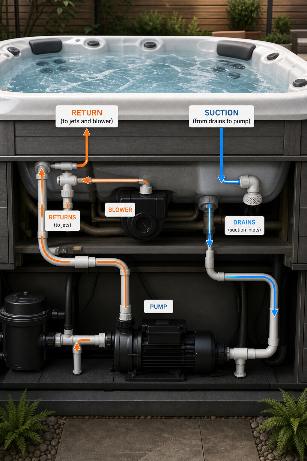
Inward plumbing draws water from the bottom drains and a skimmer, then pushes it into the pump. Outward plumbing sends water from the heater back out to the jets and any air‑injection blower. The two styles appear as opposite arrows on the plan.
Inward setups often label the suction side as “IN” and show a short, wide pipe that feeds directly into the pump. Outward lines are labeled “OUT” and branch into multiple jet manifolds. Some manufacturers combine both in a hybrid diagram , you’ll see a single line that splits after the pump, one branch returning to the jets, another feeding the blower.
Video walkthroughs on YouTube illustrate the difference. The inward path usually runs through a check valve that stops water from flowing back into the pump when it’s off. The outward path may include an air‑injection valve that mixes air with water for a bubbling effect. Spot these symbols , a check valve looks like a “V” with a line, while an air valve is a small circle with a “A” inside.
Pro Tip: when you sketch your own version, draw the inward line in blue and the outward line in red. The color contrast lets you verify that every pipe has a clear start and finish.
Bottom line: if the arrows on your diagram don’t form a closed loop, the plan is missing a piece , likely a valve or a check valve.
Step 5: Create Your Own Plumbing Diagram Sketch
Now that you’ve decoded the symbols, it’s time to draw a clean version you can use for service calls or DIY upgrades. Grab graph paper or a simple drawing app. Start with the shell outline , a rectangle or oval labeled “Tub.”
Place the pump near the bottom center. Draw a short line from the pump to a circle labeled “F” for filter. From the filter, split the line to two branches: one to the heater (label “H”) and one that loops back directly to the jet manifold (label “J”). Add arrows to show flow direction , arrows pointing toward the pump on the inlet side, away from the heater on the outlet side.
Include any check valves, air injectors, or diverter valves you saw in the original plan. Use the same symbols as the manufacturer’s diagram so a technician can read yours without guessing.
Luxury Hot Tubs offers a free printable template on its website that matches Caldera’s layout. Hot Tub Winterization: Step‑by‑Step Guide – Luxury Hot Tubs includes a blank diagram you can print and fill in with your own measurements. That template ensures you use the correct line widths and valve symbols.
When you finish, double‑check the loop: the inlet arrow should lead to the pump, through the filter and heater, and back out to the jets. If any line ends without an arrow, you’ve missed a connection.
Bottom line: a clear sketch saves time when you call a service tech , they’ll know exactly which pipe needs attention.
FAQ
What does a hot tub plumbing diagram actually show?
A hot‑tub plumbing diagram maps the flow of water from the tub, through the pump, filter, heater, and back out to the jets, using symbols and arrows to indicate each component and direction.
How can I tell if my diagram is a parallel or series layout?
If the diagram shows two separate lines from the pump to two heaters, it’s a parallel layout; if one line runs through one heater and then the next, it’s a series layout.
Why is the flow switch important?
The flow switch makes sure enough water is moving before the heater turns on, preventing dry‑fire damage to the heating element.
Can I use a generic sketch instead of the manufacturer’s diagram?
You can, but match the symbols and line widths to the original plan; otherwise a technician might misread your sketch and waste time.
Do I need a professional to read my hot tub plumbing diagram?
You don’t need a pro to read it, but a certified technician can verify your sketch and spot hidden issues like missing check valves.
Reading a hot‑tub plumbing diagram doesn’t have to be a mystery. Start by spotting the core components, trace the water’s path, note the heater‑pump layout, distinguish inward from outward lines, and then draw a clean version you can hand to a tech. Need a printable template? Grab Luxury Hot Tubs’ free diagram sheet and get your spa’s plumbing under control today.